Points from 5G 3GPP specs
By Aravind
This is just a collection of notes reading the 3GPP specs. you can download the whole spec from 3gpp.org. most points if not all are from various docs mentioned in the references section.
Architecture shift
- cloud native leveraging NFVs and software defined networking.
- Separation of control plane (CP) and Userplane (UP)
- Enable network separation (slicing). I.e. create logical slices for various services
- Service based architecture. each network function interacts with the other either directly or via a service proxy.
- converged architecture for wireline and wireless
- wireline would leverage the same 5GC (5G core) via an AGF (access gateway function)
- applications such as fixed wireless access for home broadband
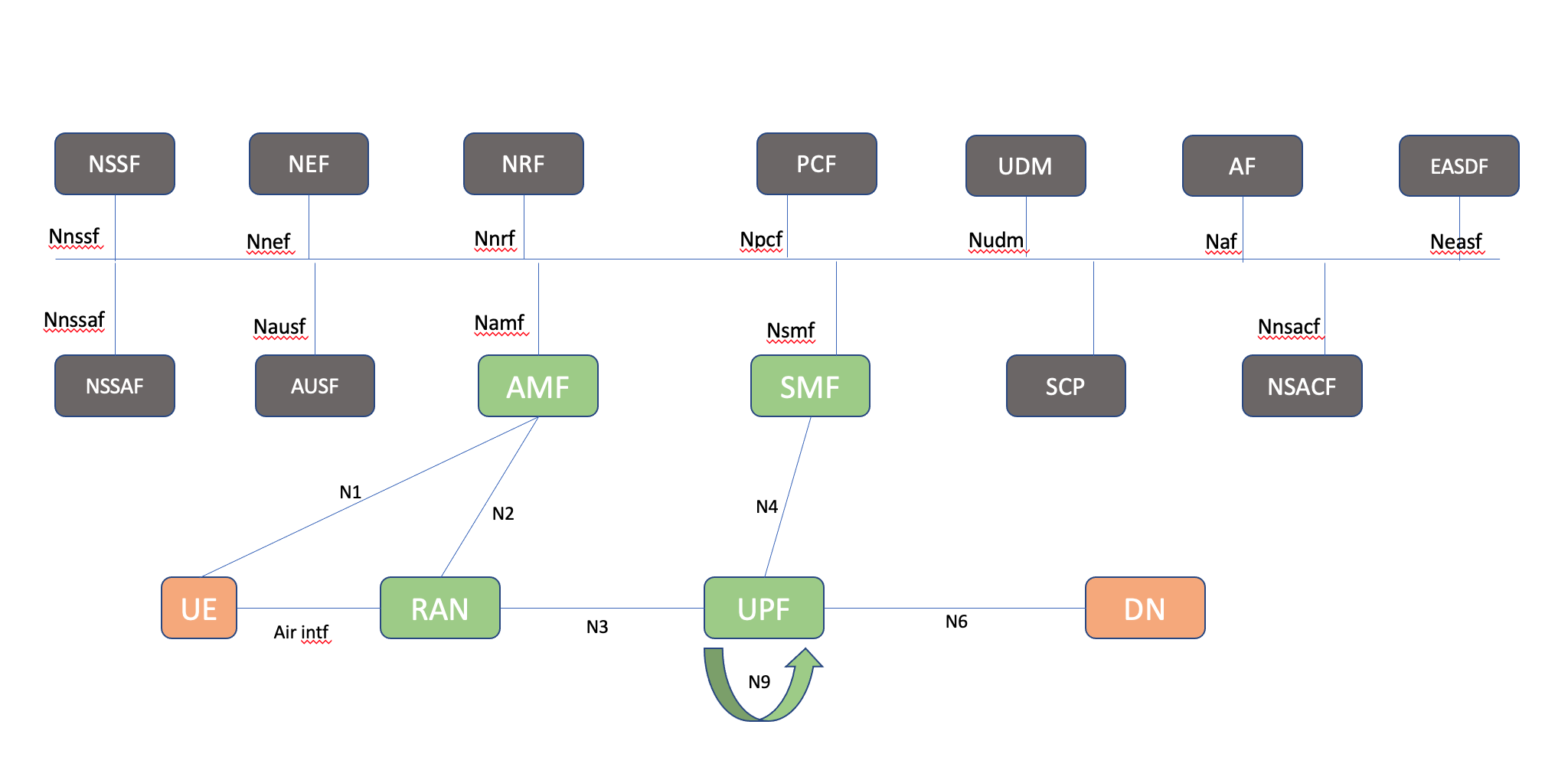
Network functions in 5G
- Authentication Server Function (AUSF).
- Access and Mobility Management Function (AMF).
- Data Network (DN), e.g. operator services, Internet access or 3rd party services.
- Unstructured Data Storage Function (UDSF).
- Network Exposure Function (NEF).
- Network Repository Function (NRF).
- Network Slice Admission Control Function (NSACF).
- Network Slice-specific and SNPN Authentication and Authorization Function (NSSAAF).
- Network Slice Selection Function (NSSF).
- Policy Control Function (PCF).
- Session Management Function (SMF).
- Unified Data Management (UDM).
- Unified Data Repository (UDR).
- stores information such as (subscription data, policy data , structured data for exposure, application data)
- User Plane Function (UPF).
- UE radio Capability Management Function (UCMF).
- Application Function (AF).
- User Equipment (UE).
- (Radio) Access Network ((R)AN).
- 5G-Equipment Identity Register (5G-EIR).
- Network Data Analytics Function (NWDAF).
- CHarging Function (CHF).
- Time Sensitive Networking AF (TSN AF).
- Time Sensitive Communication and Time Synchronization Function (TSCTSF).
- Data Collection Coordination Function (DCCF).(Can be hosted on NWDAF)
- Analytics Data Repository Function (ADRF). (Can be hosted on NWDAF)
- Messaging Framework Adaptor Function (MFAF).
- Non-Seamless WLAN Offload Function (NSWOF).
- Service communicatio proxy (SCP)
- Security edge protection proxy (SEPP)
Reference points
- N1: Reference point between the UE and the AMF.
- N2: Reference point between the (R)AN and the AMF.
- N3: Reference point between the (R)AN and the UPF.
- N4: Reference point between the SMF and the UPF.
- N6: Reference point between the UPF and a Data Network.
- N9: Reference point between two UPFs.
- N5: Reference point between the PCF and an AF or TSN AF.
- N7: Reference point between the SMF and the PCF.
- N8: Reference point between the UDM and the AMF.
- N10: Reference point between the UDM and the SMF.
- N11: Reference point between the AMF and the SMF.
- N12: Reference point between AMF and AUSF.
- N13: Reference point between the UDM and Authentication Server function the AUSF.
- N14: Reference point between two AMFs.
- N15: Reference point between the PCF and the AMF in the case of non-roaming scenario, PCF in the visited network and AMF in the case of roaming scenario.
- N16: Reference point between two SMFs, (in roaming case between SMF in the visited network and the SMF in the home network).
- N16a: Reference point between SMF and I-SMF.
- N17: Reference point between AMF and 5G-EIR.
- N18: Reference point between any NF and UDSF.
- N19: Reference point between two PSA UPFs for 5G LAN-type service.
- N22: Reference point between AMF and NSSF.
- N23: Reference point between PCF and NWDAF.
- N24: Reference point between the PCF in the visited network and the PCF in the home network.
- N27: Reference point between NRF in the visited network and the NRF in the home network.
- N28: Reference point between PCF and CHF.
- N29: Reference point between NEF and SMF.
- N30: Reference point between PCF and NEF.
- N31: Reference point between the NSSF in the visited network and the NSSF in the home network.
- N32: Reference point between a SEPP in one PLMN or SNPN and a SEPP in another PLMN or SNPN; or between a SEPP in a SNPN and a SEPP in a CH/DCS, where the CH/DCS contains a UDM/AUSF
- N33: Reference point between NEF and AF.
- N34: Reference point between NSSF and NWDAF.
- N35: Reference point between UDM and UDR.
- N36: Reference point between PCF and UDR.
- N37: Reference point between NEF and UDR.
- N38: Reference point between I-SMFs and between V-SMFs.
- N40: Reference point between SMF and the CHF
- N41: Reference point between AMF and CHF in HPLMN.
- N42: Reference point between AMF and CHF in VPLMN.
- N43: Reference point between PCFs
- N50: Reference point between AMF and the CBCF.
- N51: Reference point between AMF and NEF.
- N52: Reference point between NEF and UDM.
- N55: Reference point between AMF and the UCMF.
- N56: Reference point between NEF and the UCMF.
- N57: Reference point between AF and the UCMF.
- N58: Reference point between AMF and the NSSAAF.
- N59: Reference point between UDM and the NSSAAF.
- N60: Reference point between AUSF and NSWOF.
- N80: Reference point between AMF and NSACF.
- N81: Reference point between SMF and NSACF.
- N82: Reference point between NSACF and NEF.
- N83: Reference point between AUSF and NSSAAF.
- N84: Reference point between TSCTSF and PCF.
- N85: Reference point between TSCTSF and NEF.
- N86: Reference point between TSCTSF and AF.
- N87: Reference point between TSCTSF and UDR.
- N88: Reference point between SMF and EASDF.
5G identifiers
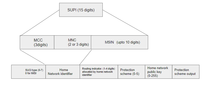
- each sim card/ue is allocated an IMSI (International mobile subscriber identity) in LTE and called as SUPI (subscriber permanent identifier) in 5G. This is unique
- Sim cards are assigned a GUTI (Globally unique temporary identification ) which are frequently changing when talking to the radio
- sometimes authentication is not possible with GUTI
- first time registration with this could be an issue where resolving IMSI/SUPI from TMSI/GUTI because the GUTI would not be allocated.
- solution to this is reveal long term identity which leads to attacks like IMSI catches. Hence 5g systems prohibit this method of allowing clear text to be transmitted over radio. Hence the UE would now use SUCI (subscriber concealed identifier) which is encrypted.
- ue will not send SUPI (Subscriber Permanent identifier) over air intf to gNB
- ue will send SUCI (subscriber concealed identifier) which is an encrypted version of SUPI
- encyrption keys would be in UDM which would be used to decrypt by trusted NFs
- only MSIN part of the SUPI gets concealed while home network identifier (MCC/MNC) gets transmitted in plain text.
AMF (Acess and Mobility Function)
- Controls which UE can access the core to exchange traffic with DN. Terminates all control plane of different access networks on 5GC.
- manages mobility of UE when they roam between gNBs providing session continuity
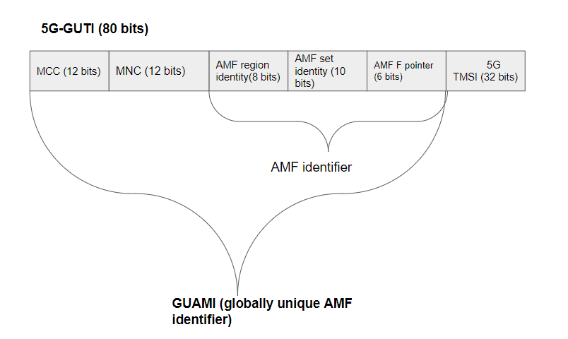
- Once the UE is successful in registration, the AMF will allocate the 5G-GUTI (Globally Unique Identifier)
- The AN then selects an AMF that maintains the UE context. If it was previously registered, uses GUAMI derived from the GUTI and enables AMF to correlate the UE request to the existing U-Context.
SMF (Session management function)
- Keeps track of PDU sessions and QOS flows to ensure the status of UE is in sync with network functions in control and user plane
- receives information from PCC (Policy charging control) rules from PCF (policy charging function) and convert PCC to SDF templates, QOS rules and profiles for UPF, gNB, UE for QOS flow establishment, modifications etc.
- establishes PFCP session with UPF on per PDU basis
- The PFCP session contains Packet Detection Information (PDI) in a Packet Detection Rule (PDR) to establish/modify the N4 PFCP session.
PFCP (Packet Forwarding Control Packet)
- rules are unique per session and are not shared with other sessions.
- Each PFCP session contains the below
- F-SEID (Fully qualified Session ID)
-
PDU session type (IPv4 IPv6 IPv4v6 Unstruct) - DNN (Data Network name.. in 4G LTE, this was called APN)
- PDR
- PDR ID
- PDI
- Traffic end point ID
- FAR-ID reference
- FAR (Forwarding action rule)
- FAR-ID
- Forwarding params
- Network instance
- Outer header creation
- description (GTPoUDP, IPv4, IPv6..)
- TEID, outer-IP
- C/S Tag, UDP port number for N6
- Forwarding policy
UPF (User plane function)
- userplane part of the 5G network. Traffic from UE are terminated here over a GTP-U tunnel (N3) and then offer connectivity to the data network over N6 interface which is IP based.
- Enforces QOS on UE uplink and downlink traffic in 5GC using SDF(Service Data Flow) templates sent by SMF using N4 PFCP (packet forwarding control packet) interface for the UE
- GTP-U is used in N3 and N9 interfaces.
UDM (Unified data management)
- store UE encryption key to decrypt the UE’s SUCI (Subscriber concealed Identifier) to SUPI (Subscriber permanent Identifier)
- stores UE subscription data
AUSF (Authentication server function)
- offer services to UDM to authenticate UEs to access the 5G services.
PDU sessions
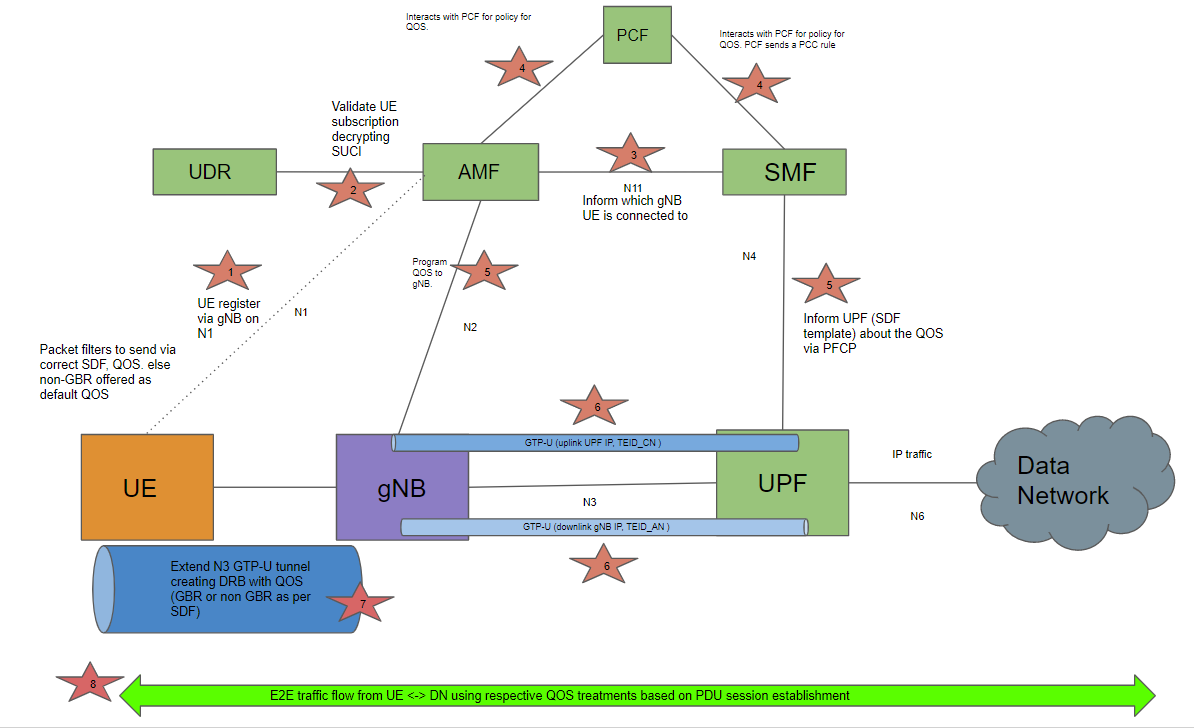
- when ue turns on, ue will perform registration with AMF to authenticate itself. The UDM would help authenticate the validity of the subscriber. This consists of various steps between UE, AMF, UDM to validate the SUCI.
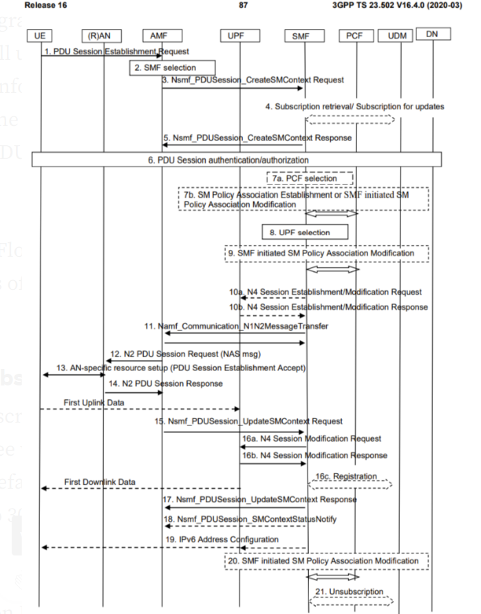
- once authentication is completed, UE sends a PDU session establishment request to AMF via gNB over N1 interface. This will create a QOS flow (5QI) between UE and the DN (data network). The UE can then use the QOS flow inside the established PDU session to exchange traffic with DN (internet, intranet in case of custom DNN/APN).
- QOS flows are the lowest level of granularity where charging can be applied
- A Data Radio Bearer (DRB) is established by the gNB to the UE to extend the UPFs N3 GTP-U tunnel to the UE
- Default QOS flow is non-GBR (Guaranteed bit rate) QOS flow without packet filters
- if uplink/downlink traffic do not match packet filters, default QOS flow would be used to foward traffic to a from DN
- Default QOS can also be used to signal an AF (application function) to establish a GBR. The application servers could be voice/video
- an SDF is a traffic stream between UE and data network where SDF requirements are satisfied by the QOS flow carrying the SDF.
- UE can signal a GBR flow using default QOS to video server (AF). AF will initiate a QOS flow setup to the PCF, the PCF inturn generates a PCC rule to SMF. The SMF further updates the UPF with a PDU session modification request to augment the UE’s PDU session either by creating a new QOS flow or modify an existing flow.
- in case of multi-tasking different apps may require same QOS GBRs. So 2 SDFs could be supported via a session modification procedure. Process to map a traffic stream or SDF onto suitable QOS flow is called SDF binding
- For successful PDU sessions between UE and DN
- bidirectional DRB between UE and gNB
- two unidirectional GTP-U tunnels to form a bidirectional N3 GTP-U tunnel between gNB and UPF
- gNB (Access Node {AN}) and UPF (Core Node {CN})
- AN tunnel has gNB IP address, UEs TEID_an which is the GTP-U tunnel end point at the gNB. This is teh tunnel the UPF has to forward traffic (UE downlink traffic) to UE via gNB
- Core node tunnel on UPF has UPF IP address and UEs TEID_cn which is the GTP-U tunnel end point at the UPF. This is the tunnel the gNB use to forward (UE uplink) UE traffic to the DN via UPF
- tunnel per UE is created. example: 2 gNB each serving 5 UEs, then totally (2x5=10) 10 UEs exist and there would be 10 TEID_an and 10 TEID_cn tunnels created on gNB and UPF accordingly.
- UPFs IP and UE TEID_cn together called PDU session anchor (PSA) for UE
- this is needed when UE roams between gNBs. SMF will inform UPF new AN tunnel to forward UPF traffic downlink to UE. SMF will also inform gNB2 the existing PSA so that gNB2 can continue forwarding the UE traffic to UPF to maintain session connectivity
- this is needed when UE roams between gNBs. SMF will inform UPF new AN tunnel to forward UPF traffic downlink to UE. SMF will also inform gNB2 the existing PSA so that gNB2 can continue forwarding the UE traffic to UPF to maintain session connectivity
SSC modes
Session and service continuity helps ensure the service is uninterrupted if there is change in IP address on the UE or the UE anchors to a different core. The PDU session is configured to use an SSC mode.
- ue can request an SSC mode during the PDU session establishment request
- SMF specifies the allocated mode within the PDU sssion establishment accept
- Mode 1 & 2 -> IP/Ethernet , 3 -> IP only
- SMF receives the supported SSC modes per DNN and S-NSSAI as part of the subscription from UDR
- happens as part of NAS signalling (ue - amf)
Mode1 (preserve IP)
- IP address (v4/v6) is preserved.
- the anchoring UPF remains (same UPF is used) until the PDU session is released by the UE
Mode2 (New session)
- PDU session can be released
- allocated IP address is released
- new PDU session created with new UPF
Mode3 (new session setup then release old session)
- update the IP address to the new anchor UPF
- preserve connectivity by still having the older session
- once connectivity to new UPF is established, release the older session
- only IP based PDU sessions are supported
References
[5g